Compromise joint bars are one kinds of special rail joint bar. As we know, normal rail joint bars are the components involved in railway applications that connect different sections of rails together while maintaining gauge and keeping the alignment of rail surfaces. Unlike normal rail joint bar, compromise joint bars are used for joints of abnormal rails.
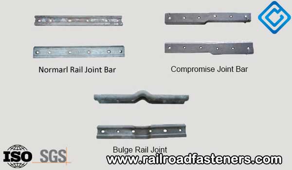
Compromise joint bars are designed to consist of two separate bars— an outside joint bar and an inside joint bar. These bars are designed to smoothly match the gauge-head face of two rails. These special joint bars are usually sold in sets, consisting of four different bars. Bars are identified by standing in the centre of the track between the "heavy" or high rails facing the direction of the "light" rails, and indicate the joint to the right as the "right hand" joint and the joint to the left as the "left hand" joint. The four bars are Left Out, Left gauge, Right gauge and Right Out.
There are two kinds of compromise joints:
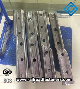
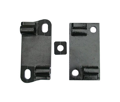
UIC60-P50 special joint bar
- Directional (Right or Left hand) compromise rail joint bar is used where a difference in the width of the head between two sections requires the offsetting of the rail to align the gauge side of the rail.
-
Non-directional (Gauge or Field Side) joint bar is used where the difference between sections is only in the heights of the head or where the difference in width of rail head is not more than 1/8" at the gauge point. Gauge point is the spot on the gauge side of the rail exactly 5/8" below the top of the rail.
To determine a left or right hand special joint bar, we must know:
- Stand between the rails at the taller rail section;
- Face the lower rail section;
- The compromise rail joint on your right is a "right hand";
- The compromise rail joint bar on your left is a "left hand".
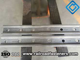
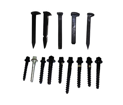
132RE special joint bar
For normal practice, it is to furnish four bolt holes to connect first two holes only in each rail. Step chairs are not included with compromise joint bars, unless specified. When we confirm both rail sections and specify drilling in each rail, we must know the number of joints required and the following compromise joint bar dimensions:
- A. Distance from end of the rail, to center-line of the first hole;
- B. Center-line of the first hole, to center-line of the second hole;
- C. Center-line of the second hole, to center-line of the third hole (where 6-hole bars are used);
- D. The diameter of bolt hole (or bolt size);
- E. Elevation of bolt hole (center-line of bolt hole above base) on a non-standard rail.
Compromise Joint Bar Dimensions
Below, we can find more special joint bars available at AGICO
|
No. |
Type |
Material |
Unit weight |
Remark |
|
1 |
136RE-115RE |
55# |
27.5 |
4pcs per set |
|
2 |
136RE-132RE |
55# |
26.7 |
2pcs per set |
|
3 |
141RE-136RE |
55# |
26.7 |
2pcs per set |
|
4 |
141RE-132RE |
55# |
26.7 |
2pcs per set |
|
5 |
100-8 of 1/8〞vertical off |
55# |
15.6 |
2pcs per set |
|
6 |
100-8 of 3/8〞vertical off |
55# |
15.6 |
2pcs per set |
|
7 |
UIC60-P50 |
55# |
23 |
2pcs per set |
|
8 |
BS80A-115RE |
55# |
20 |
2pcs per set |
|
9 |
UIC60 thermit welded joint |
55# |
18 |
2pcs per set |
|
Material and bar length can be customized upon buyer request. |
||||